From 23rd to 25th October 2018, or 4 months after Metrology Camera System (MCS) was tested on Subaru telescope, we have finally carried out 2nd test of MCS on the Subaru telescope. Since we used the telescope at night this time, this is the first engineering run with PFS instrument!
MCS is the instrument to measure the positions of the fibers on the prime focal plane. MCS is equipped with a large-format CMOS sensor to take a snapshot of ~2400 fibers in one exposure, which are illuminated from the Spectrograph Modules (we call it “back-illumination”). The centroids of fiber spots are measured quickly. Our goals of this run were to finalize the optical alignment inside MCS, and optimize the axial position of MCS with respect to the Subaru Prime Focus. We also aimed at studying the effect of the atmosphere inside the telescope dome called “dome seeing” on centroid measurement in observing condition, and investigating the optics distortion which is important to transform the MCS image coordinates to prime focal plane coordinates.
Since other PFS subsystems haven’t been delivered yet, we have installed the pinhole mask on the prime focal plane and lit them up, as shown in the photos below, in order to mimic “back-illuminated” fibers.
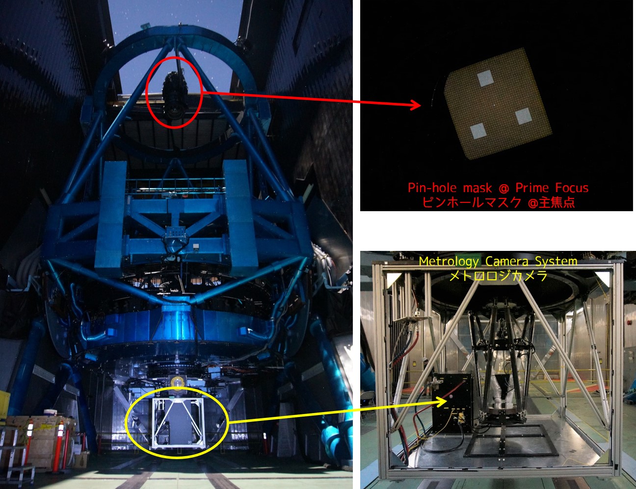
Metrology Camera system in the engineering run. Pinhole mask (top-right) was installed to the Prime Focus.
About 10 PFS members participated in the engineering run from ASIAA (Academia Sinica Institute of Astronomy and Astrophysics, Taiwan), who has developed the MCS, Princeton University (the USA), who has developed instrument control software packages, and the PFS Project Office at Kavli IPMU, the University of Tokyo (Japan).
Investigating the spots of the pinhole mask on MCS, we adjusted the MCS mirror orientation in order to obtain the same image quality as we had when we aligned the camera at the Summit. After finishing the alignment, we have obtained thousands of images to study the dome seeing effect and the optical distortion. We will analyze the data in detail and tune the system for measuring fiber positions.
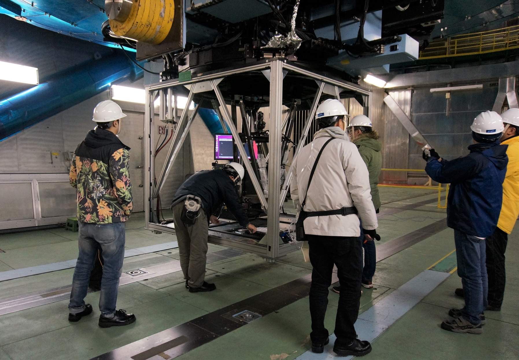
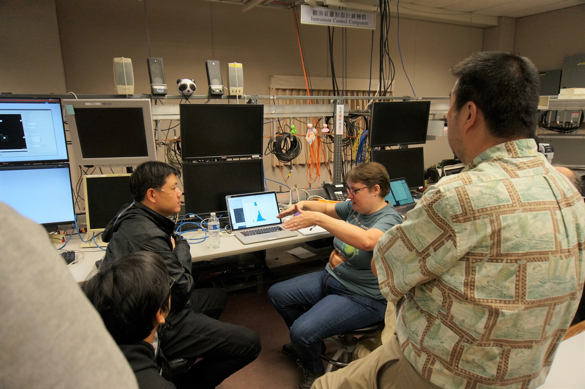
Snapshots oh the engineering run.
Left: Carrying out the optical alignment. Right: Discussing the result of quick-analysis.